Normas de tolerancia para piezas de moldes de estampado de precisión: Referencias dimensionales generales de la industria
Apr 29, 2026
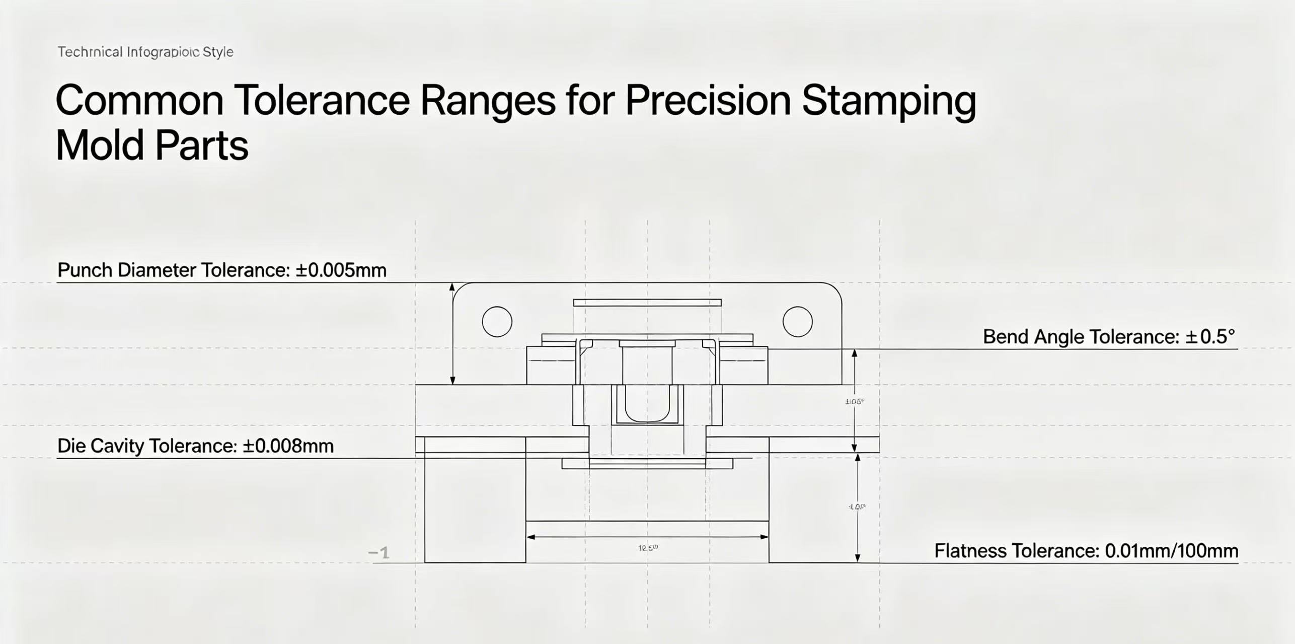
En la fabricación de precisión, incluso las desviaciones menores pueden causar fallas costosas o un ensamblaje deficiente. Los estándares de tolerancia y los datos dimensionales son fundamentales para la confiabilidad. molde de estampado de precisiónrendimiento, lo que permite obtener componentes consistentes y de alta calidad para los sectores automotriz, aeroespacial y electrónico. ¿Cuáles son los estándares de tolerancia para? Piezas de moldes de estampado de precisión?Las normas de tolerancia definen las variaciones permitidas en pieza del moldetamaño, forma y posición, lo que garantiza una funcionalidad e intercambiabilidad perfectas. A diferencia del estampado general, el estampado de precisión requiere tolerancias estrictas —normalmente de ±0,001 a ±0,005 pulgadas (±0,025 a ±0,127 mm)— basadas en el consenso de la industria, el comportamiento del material y las necesidades del producto final. Estas normas equilibran dos objetivos clave: garantizar la intercambiabilidad de las piezas (para facilitar los cambios de lote/fabricante) y equilibrar la precisión con la facilidad de fabricación, evitando tolerancias excesivamente estrictas que aumenten los costes innecesariamente. Referencias dimensionales generales de la industria: La base del control de toleranciasLos datos dimensionales son puntos, líneas o planos de referencia que estandarizan las mediciones de tolerancia. Sin datos claros, las tolerancias precisas pierden sentido, lo que provoca desalineación y piezas no conformes. La industria utiliza un "marco de referencia de datos (DRF)" con tres datos principales: 1. Datum primario (Datum A)La referencia más importante (a menudo una superficie plana como la superficie de separación del molde o la base de la placa base) garantiza la alineación con la prensa de estampado. Limita tres grados de libertad (traslación en X, Y y Z) y establece la línea base para todas las mediciones. 2. Datum secundario (Datum B)Perpendicular al plano de referencia principal, restringiendo dos grados de libertad adicionales (rotación X/Y). Generalmente se trata de una superficie lateral, una ranura o un pasador (por ejemplo, el lateral del vástago de un punzón) para reforzar la orientación con respecto al plano de referencia A. 3. Datum Terciario (Datum C)Perpendicular a los planos de referencia primario y secundario, limitando el grado de libertad final (rotación en Z). Un pequeño elemento (por ejemplo, un orificio o una muesca) que ajusta con precisión la posición, asegurando la restricción total de la pieza.Principales normas del sector que rigen las tolerancias y los sistemas de referencia.Los estándares globales proporcionan un lenguaje común para los fabricantes, lo que garantiza la coherencia de la cadena de suministro y una comunicación clara del diseño: 1. ASME Y14.5 (GD&T)El estándar de referencia para el dimensionamiento y la tolerancia geométrica (GD&T), que establece símbolos y reglas para las características de las piezas. Actualizado en 2018 (reafirmado en 2024), hace hincapié en los puntos de referencia para el control de las tolerancias geométricas y se utiliza ampliamente en los sectores automotriz, aeroespacial y electrónico. 2. ISO 2768 (Tolerancias generales)Define tolerancias generales para características lineales/angulares/geométricas no marcadas, con cuatro clases (F/M/C/V). La mayoría piezas de moldes de precisiónUtilice clases finas/medias, simplificando los dibujos al reducir el marcado de tolerancias redundantes.3. DIN 6930 (Piezas de acero estampado)Diseñado específicamente para acero estampado, tiene en cuenta el comportamiento del metal sometido a cizallamiento (por ejemplo, en el rodillo de troquel) que afecta a las tolerancias. Especifica cuatro niveles de precisión para dimensiones, concentricidad y simetría, muy utilizados en los sectores automovilístico e industrial europeos. 4. ISO 8062-3 (Piezas moldeadas)Se centra en las tolerancias dimensionales y geométricas de las piezas moldeadas (incluidos los moldes de estampado de precisión), definiendo los grados y los márgenes de mecanizado para lograr una coherencia global. Rangos de tolerancia comunes para piezas de moldes de estampado de precisiónLos rangos típicos equilibran la precisión y el costo, y varían según la función de la pieza, el material y el proceso:Punzones y matrices: Superficies críticas (puntas de punzón, cavidades de matriz): ±0,001–±0,005 pulgadas (±0,025–±0,127 mm); no críticas: ±0,005–±0,010 pulgadas (±0,127–±0,254 mm).Pasadores guía y casquillos: Diámetro/concentricidad: ±0,0005–±0,001 pulgadas (±0,0127–±0,0254 mm); holgura: 0,0005–0,001 pulgadas para evitar atascos.Bases de moldes: Superficies de montaje/referencia: ±0,001–±0,002 pulgadas (±0,0254–±0,0508 mm) para la alineación de la prensa.Perforación/Tapado: Borrado: ±0,05 mm; perforación: ±0,05 mm (diámetro/posición); estampado de precisiónSe reduce a ±0,025 mm.Factores que influyen en la selección de toleranciaLa selección de tolerancias requiere equilibrar cuatro factores clave: Función del producto finalLas piezas críticas o de seguridad (médicas o aeroespaciales) requieren tolerancias más estrictas (a menudo de ±0,001 pulgadas) que los componentes no críticos. Propiedades del materialLos materiales más blandos (aluminio, cobre) mantienen mejor las tolerancias que los materiales duros (acero de alta resistencia), lo que puede requerir una compensación de la matriz para evitar la recuperación elástica. Proceso de fabricaciónLos troqueles progresivos y las prensas servoaccionadas permiten tolerancias más ajustadas; los troqueles de holgura reducida (5-10% del espesor del material) mejoran el control.Costo: Las tolerancias más estrictas que ±0,001 pulgadas requieren herramientas especializadasy el control de la temperatura, lo que eleva los costos exponencialmente. En resumen, comprender las referencias dimensionales y los estándares de tolerancia generales de la industria es fundamental para optimizar el rendimiento de los moldes de estampado de precisión, reducir el desperdicio y garantizar la calidad del producto final. Al adherirse a estándares establecidos como ASME Y14.5 e ISO 2768, y al equilibrar cuidadosamente las necesidades funcionales con la facilidad de fabricación, los fabricantes pueden crear piezas de molde confiables y rentables que satisfagan las exigencias de las industrias actuales, que se caracterizan por su alta precisión. A medida que la tecnología avanza, estos estándares seguirán evolucionando, pero su propósito fundamental —proporcionar un marco consistente y confiable para el control de tolerancias— seguirá siendo la piedra angular de la fabricación de estampado de precisión.


 Red IPv6 compatible